

 русский
 عربى

Industry News
Home / News / Industry News / CNC Wire Cut EDM Machine: Specs, Costs and Buying Guide for Mold Shops
CNC Wire Cut EDM Machine: Specs, Costs and Buying Guide for Mold Shops
 2026.10.21
 Industry News
A hardened D2 stamping die, a carbide punch, an extrusion die insert — once these parts come out of the furnace at 58 to 62 HRC, milling is over and grinding becomes slow and expensive. A CNC wire cut EDM machine solves that problem. It removes metal with a travelling wire electrode and a stream of deionized water, and it never touches the workpiece with a hard tool.
The short answer comes first: wire EDM is the right process when your geometry is a through-profile or a straight-tapered form and the tolerance is tighter than roughly ±0.01 mm. It is the wrong process for blind cavities with 3D detail, for high-volume simple parts, and for anything that does not conduct electricity. The rest of this page explains how to tell those cases apart, which specifications actually decide whether a machine fits your work, and what to check before you sign a purchase order.
Content
- 1 How a CNC Wire Cut EDM Machine Removes Metal
- 2 The Specifications That Decide Whether a Machine Fits Your Work
- 3 Where Wire EDM Earns Its Place, and Where It Does Not
- 4 Wire EDM and Sinker EDM Are Not Competitors
- 5 Buying Checklist and Running Costs
- 6 Frequently Asked Questions
- 6.1 Q1. How does a CNC wire cut EDM machine work?
- 6.2 Q2. What is the difference between wire EDM and sinker EDM?
- 6.3 Q3. What tolerance can a CNC wire cut EDM machine hold?
- 6.4 Q4. Which wire diameter should I choose?
- 6.5 Q5. Can a wire EDM machine cut hardened steel and carbide?
- 6.6 Q6. What drives the price of a CNC wire cut EDM machine?
How a CNC Wire Cut EDM Machine Removes Metal
On a wire machine, the electrode is a spool of thin wire — normally 0.10 mm to 0.33 mm brass or zinc-coated brass, or molybdenum wire where reusable wire is preferred. The wire runs from a supply spool, through tension rollers, down through an upper guide and flushing nozzle, through the workpiece, and out through a lower guide below the table. The wire never contacts the part. Instead, a controlled spark jumps the gap between wire and workpiece inside a flow of deionized water, which flushes the debris away and keeps the cut stable.
Because the wire erodes as it cuts, the kerf is always wider than the wire itself. As a working number, a roughing pass opens about 0.03 mm of gap on each side, so a 0.25 mm wire leaves a slot of roughly 0.31 mm. That same gap explains why wire EDM cannot produce a sharp internal corner: the smallest radius the process can reach is the wire radius plus the spark gap.
Most machines then finish with several passes. A high-energy roughing pass removes the bulk of the material quickly, and two to four skim passes at low energy bring the surface down to the required roughness and strip the recast layer left behind by the roughing spark. Machines that control more passes with finer energy steps hold tighter tolerance and often eliminate a secondary finishing operation. In price-sensitive markets, reusable molybdenum wire combined with multipass cutting is a common configuration, as described in supplier literature for that class of machine, because the wire can be re-threaded and reused instead of being discarded after a single run.
The Specifications That Decide Whether a Machine Fits Your Work
Wire diameter sets your smallest corner
Start here, because this number drives everything else. If your dies carry 0.1 mm internal radii, a 0.33 mm wire will never produce them, however good the generator is. The relationship is simple enough to calculate on the back of an envelope.
The trade-off is speed and reliability. Thinner wire cuts more slowly, breaks more easily, and demands finer flushing and better wire guides. Choose the largest diameter your tightest corner allows, and only step down when the geometry forces you to.
Travel, table load and Z height
Work out the largest part you expect to cut, add the fixture and the nozzle clearance, and then check the Z stroke — not just the X and Y travel. A machine that fits the plate but not the fixture will sit idle. Table load becomes relevant as soon as you cut a stack of small parts or a heavy die block in one setup.
Taper capability
A two-axis machine cuts straight walls only. A ±15° taper head covers die relief and draft angles; ±30° handles most extrusion and injection work. Taper angle is always quoted at a specific workpiece height, and the usable angle falls as the part gets taller, so ask for the taper graph rather than the headline number.
Generator, pass control and anti-electrolysis
The generator decides cutting speed, surface finish and the thickness of the recast layer. Check how many passes the control supports, whether parameters are selected automatically for the material and wire combination, and whether the machine offers anti-electrolysis settings. Those settings matter if you cut carbide or sintered tool steel, where the cobalt binder is vulnerable to attack in the dielectric.
Automation
Automatic wire threading and re-threading, a wire chopper, submerged cutting and unattended restart after a wire break are the features that decide whether the machine runs overnight or waits for an operator in the morning.
Where Wire EDM Earns Its Place, and Where It Does Not
Wire EDM sits at the tight end of the tolerance range. It is the standard process for stamping dies and punches, progressive die plates, extrusion and drawing dies, carbide inserts, fine slots, thin walls, and small batches of hardened aerospace or medical parts where the alternative would be annealing the component, machining it, and re-hardening it with all the distortion risk that brings.
In a die shop the workflow usually runs the other way round as well: rough the profile on a vertical machining center leaving 0.2 to 0.5 mm of stock, send the part for heat treatment, then finish on the wire machine. The point of that pre-machining step is not to cut hard steel — it is to remove the bulk of the material while the block is still soft, cheap and easy to cut, so the wire only has to make the final pass.
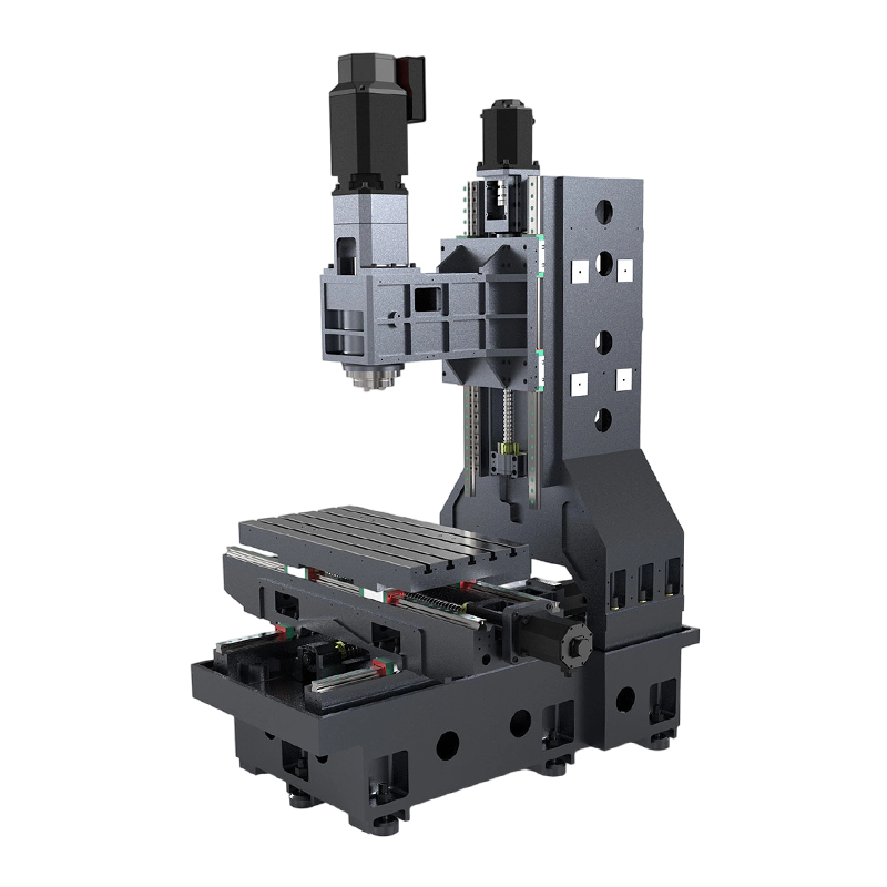 Economical VMC EV850 Vertical Machining CenterPre-machining option for wire EDM workflows, this economical vertical machining center removes bulk stock before heat treatment and final wire finishing.View Product →
Wire EDM is the wrong answer in three situations. Blind cavities with 3D form are physically out of reach for a wire. High-volume simple profiles are faster and cheaper to mill. Very deep, narrow cuts suffer poor flushing, which slows the cut and increases wire breakage, so thin tall ribs and awkward stack-ups deserve a test cut before you commit to the process at all.
Wire EDM and Sinker EDM Are Not Competitors
Many first-time buyers assume they have to choose between the two EDM processes. In practice, most mold and die shops run both, because they solve opposite problems. Wire EDM is unbeatable on through-profiles and sharp-cornered openings. Sinker EDM is the only way to burn a blind cavity, a rib or a 3D form into a hardened block. If you are still weighing the two, this comparison of wire EDM and sinker EDM settles the question in ten minutes.
| Point of comparison | CNC wire cut EDM | CNC die-sinking EDM |
|---|---|---|
| Cutting tool | Wire electrode, 0.10 to 0.33 mm | Machined graphite or copper electrode |
| Geometry | Through-profiles, tapered walls, punch and die openings | Blind cavities, ribs, deep 3D detail |
| Smallest internal corner | Wire radius plus spark gap, roughly 0.08 to 0.20 mm | Set by electrode detail, often finer |
| Tooling cost | Low: the wire is disposable | Higher: every electrode must be milled and dressed |
| Typical tolerance | ±0.003 to ±0.005 mm on a well-kept machine | ±0.01 to ±0.02 mm |
| Best fit | Stamping dies, extrusion dies, carbide, thin walls | Mold cavities, deep ribs, textured surfaces |
For those blind-cavity jobs, the companion to a wire machine is a sinker. A CNC die-sinking EDM machine burns the cavity with a shaped electrode and reaches detail that no wire can, which is why the two are usually bought as a pair rather than as substitutes for one another.
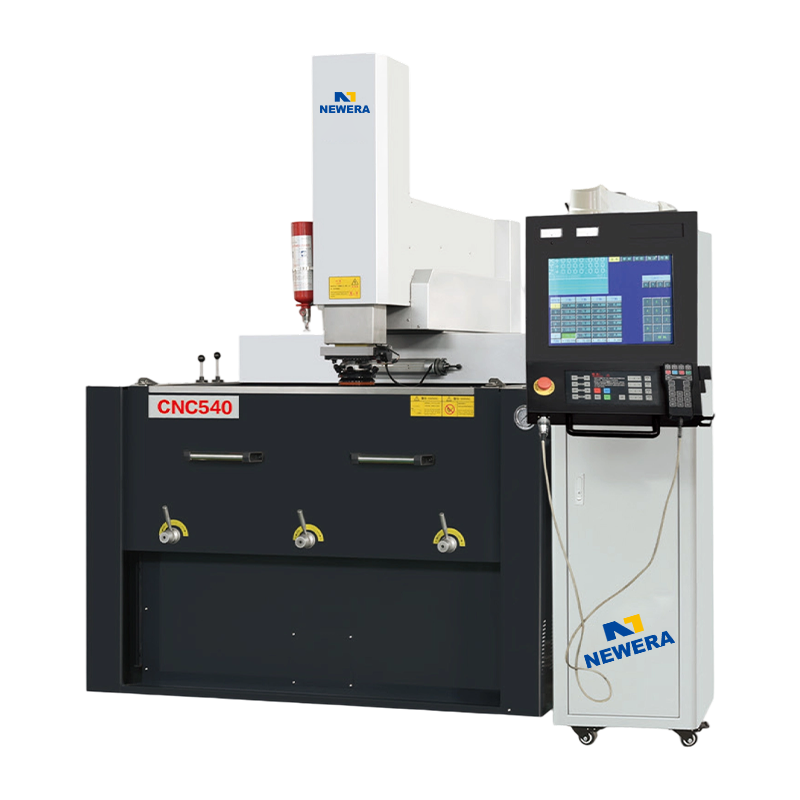
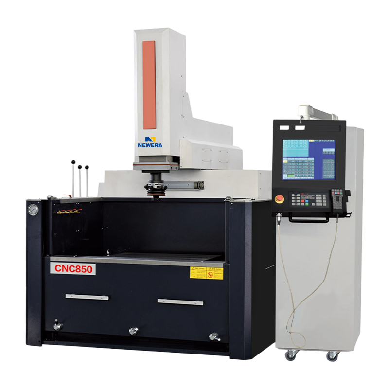
 CNC 650 EDM Die Sinking Machine Sinker EDMA companion sinker EDM for blind cavities, placed alongside wire machines for die-shop workflows requiring shaped-electrode detail.View Product →
The electrode has to be machined first
A sinker is only as good as the electrodes it burns with. Graphite blanks are milled to shape before they ever reach the EDM tank, and that work needs a machine built for the dust and the wear. Graphite engraving and milling machines run higher spindle speeds, sealed guideways and dedicated dust extraction, so the electrode geometry that leaves the spindle is the geometry that burns into the die.
 NE6050 Graphite Engraving and Milling MachineGraphite machining option for preparing shaped electrodes before sinker EDM, supporting die-shop workflows where electrode geometry matters.View Product →
Buying Checklist and Running Costs
A wire EDM is judged on what it holds after eight hours of cutting, not on the number printed in the brochure. Use this list when you evaluate a machine:
- Ask for a test cut on your own material, with your own geometry, and measure the result — not a demo part prepared by the supplier.
- Check positioning accuracy and repeatability after the machine has been running for a full shift, not cold.
- Confirm how many passes the control supports and whether the parameters are selected automatically or typed in by hand.
- Verify automatic wire threading, re-threading after a break, and whether the wire chopper handles the used wire without operator attention.
- Price the consumables before you buy: wire, filters and resin, deionized water treatment, wire guides, nozzles, and the power and chiller load.
- Ask who services the machine locally, what the spare-part lead time is for guides, nozzles, pumps and the control, and whether remote diagnostics are included.
- Check the software side — DXF import, nesting, taper programming and whether the post-processor matches how your shop actually prepares drawings.
- Confirm the installation requirements: floor space, foundation, water supply quality, ambient temperature control and ventilation.
None of these points require a bigger machine. They require a machine that was specified for your parts, and a supplier who will still answer the phone in year three.
Frequently Asked Questions
Q1. How does a CNC wire cut EDM machine work?
A thin wire, usually 0.10 to 0.33 mm brass or molybdenum, travels between two guides and erodes the workpiece with controlled electrical sparks inside a flow of deionized water. The wire never touches the part, so there is no cutting force.
Q2. What is the difference between wire EDM and sinker EDM?
Wire EDM cuts through-profiles with a moving wire and almost no tooling cost. Sinker EDM burns a shaped cavity with a machined electrode. Through-opening: use wire. Blind 3D cavity: sinker EDM is the only option.
Q3. What tolerance can a CNC wire cut EDM machine hold?
A well-maintained machine with thermal compensation typically holds ±0.003 to ±0.005 mm, provided flushing is good and shop temperature is stable. In a normal workshop without temperature control, ±0.01 mm is a realistic figure.
Q4. Which wire diameter should I choose?
Use the largest wire your smallest internal radius allows. A 0.25 mm wire cuts faster and breaks less often. A 0.10 mm wire is for radii under roughly 0.1 mm and thin walls, but it cuts more slowly and needs finer flushing.
Q5. Can a wire EDM machine cut hardened steel and carbide?
Yes, as long as the material conducts electricity. Tool steel at 60 HRC, carbide and powder metallurgy steels are routine work. Carbide benefits from anti-electrolysis generator settings, because the cobalt binder can be attacked by the dielectric.
Q6. What drives the price of a CNC wire cut EDM machine?
Axis travel and taper capability are the largest cost drivers, followed by the generator, the number of controlled axes, automatic wire threading and submerged cutting. A two-axis machine with manual threading costs a fraction of a five-axis machine with a 30 degree taper head.
If you are interested in our products, please consult us.
CONTACT DETAILS
Nantong New Era Technology Co., LTD
- Five-star Industrial Park, Chongchuan District, Nantong City, Jiangsu Province, China
- TEL:+86-19851302688
- E-Mail: [email protected]
Products
Quick link
Mobile terminal
