

 русский
 عربى

Industry News
Home / News / Industry News / How Does EDM Machining Work? Spark Gap, Dielectric and Discharge Physics
How Does EDM Machining Work? Spark Gap, Dielectric and Discharge Physics
 2026.10.28
 Industry News
A 0.3 mm inside corner at the bottom of a 58 HRC H13 die insert is the point where milling stops being an option. The corner radius is smaller than any practical cutter, the material will kill a carbide tip in a single pass, and the feature sits too deep for a tool holder to reach. That is the job electrical discharge machining was built for.
The short answer to how EDM machining works: it removes metal with controlled electrical sparks instead of cutting force. A shaped electrode is fed toward the workpiece through a bath of dielectric fluid, a pulsed voltage breaks the fluid down across a gap of a few hundredths of a millimetre, and every discharge melts and vaporises a microscopic crater of metal. The electrode never touches the part.
Because material is removed thermally instead of mechanically, workpiece hardness stops mattering and electrical conductivity becomes the requirement. What follows is the mechanism in detail, the systems that keep it stable, and the practical numbers that decide whether EDM is the right process for a given feature.
Content
- 1 What Actually Happens in the Spark Gap
- 2 The Systems That Keep a Discharge Stable
- 3 One Discharge Cycle, Step by Step
- 4 Hardness Is Irrelevant, Conductivity Is Not
- 5 From Rough to Mirror: How Each Pass Changes the Finish
- 6 Where EDM Wins, and Where It Loses
- 7 ZNC, PNC and CNC: What the Control Level Buys You
- 8 Matching the Machine to the Work, Not the Other Way Round
- 9 Deep Cavities and Large Moulds: The Real Limit
- 10 EDM Machining: Frequently Asked Questions
- 10.1 Q1: How does EDM machining work in one sentence?
- 10.2 Q2: What is the difference between sinker EDM and wire EDM?
- 10.3 Q3: Can EDM machine hardened steel?
- 10.4 Q4: What is the spark gap in EDM machining?
- 10.5 Q5: How accurate is EDM machining?
- 10.6 Q6: What is the difference between a ZNC, PNC and CNC EDM machine?
What Actually Happens in the Spark Gap
The gap is the whole process. In finishing it is typically 0.01 to 0.05 mm across; in heavy roughing it can open to roughly 0.1 mm. That space is filled with dielectric fluid, which insulates the electrode from the workpiece until the generator decides otherwise.
When a pulse is applied, voltage climbs until the fluid can no longer hold it. A plasma channel forms across the narrowest point of the gap, current flows, and the local temperature reaches roughly 8,000 to 12,000 degrees Celsius, hot enough to melt and partly vaporise the workpiece surface. The pulse lasts microseconds. When it is switched off, the channel collapses, the molten pool implodes and throws most of its material into the fluid, and the dielectric carries the debris away.
Then it happens again. Depending on the generator, a machine can produce anywhere from a few thousand to several hundred thousand discharges per second, each one carving a crater a few microns deep. The servo system feeds the electrode forward to hold the gap constant: too close and the discharge turns into a damaging arc, too far and no spark forms at all.
One detail catches people out. On a die-sinking machine the electrode is a shaped block of copper or graphite; on a wire machine it is a moving brass wire. The physics is shared, the tooling and the applications are not, and it is worth settling the difference before specifying a machine. A comparison of sinker EDM vs wire EDM covers where each one earns its keep.
The Systems That Keep a Discharge Stable
Every EDM machine, from a manual ZNC to a fully programmable sinker, is assembled from the same building blocks. If one of them is outmatched, the others cannot compensate for it.
| System | What it controls | What goes wrong when it is weak |
|---|---|---|
| Pulsed power supply (generator) | Discharge current, pulse on-time and off-time, polarity, the settings that decide removal rate and surface finish | Unstable low-current output, drifting finish, arcing on deep ribs |
| Servo control | Gap width, and how quickly the electrode reacts to a short circuit or an open gap | The electrode hammers the workpiece or stalls, and cutting becomes slow and inconsistent |
| Electrode and fixture | The shape copied into the part; copper or graphite decides detail against speed | Oversized cavities, poor corner definition, unpredictable wear |
| Dielectric and flushing | Insulation, cooling, and removal of debris from the gap | Carbon build-up, secondary discharges, burnt corners on deep work |
| CNC control | Orbiting paths, multi-cavity programs, automatic electrode change | Manual repositioning, one cavity at a time |
One Discharge Cycle, Step by Step
Following a single pulse makes the behaviour on the control screen easier to read.
- The servo advances the electrode until the gap is roughly the width of a human hair.
- The generator raises the voltage across the gap; the dielectric holds it back until breakdown.
- A plasma channel forms and current rises in microseconds to the programmed peak value.
- The surface under the channel melts and partly vaporises, leaving a crater.
- The pulse ends, the channel collapses, and the crater implodes, ejecting molten metal into the fluid.
- Flushing carries the debris out and fresh dielectric flows in.
- Steps two to six repeat thousands of times per second while the CNC orbits the electrode to sweep out the cavity.
Schematic of a die-sinking EDM setup: a shaped electrode, submerged in dielectric fluid, burns a cavity into the workpiece. Not to scale.
Hardness Is Irrelevant, Conductivity Is Not
With no cutting force involved, EDM machines a 62 HRC die steel, cemented carbide and Inconel with the same electrode and the same fixture. There is no tool deflection, no work hardening, no chatter, and thin ribs do not flex away from the cut. The one hard requirement is that the workpiece conducts electricity.
Workpiece hardness EDM machines in one setup
Typical hardness values for common die and mould materials; EDM is unaffected by any of them.Electrode material follows the opposite logic. Copper holds fine detail and wears slowly at low currents, which is why it dominates finishing work on detailed cavities. Graphite removes more material per minute at high current and is far easier to machine into large, complex shapes, but it leaves a coarser surface and wears faster at the sharp edges that define a cavity.
Corner wear is the detail that quietly costs money. An electrode wears at its corners several times faster than across its flat faces, so a cavity that measures correctly on the first pass drifts out of tolerance as the electrode rounds off. That is why electrodes are cut undersize to allow for the spark gap and the wear allowance, and why a second finishing electrode is often cheaper than a scrapped mould.
From Rough to Mirror: How Each Pass Changes the Finish
No cavity is machined in a single pass. The first electrode does the heavy removal with high current and long discharge durations, leaving a matte, pitted surface. Later passes use the same electrode at progressively lower current and shorter on-time, so each spark carves a shallower crater on top of the previous one and the roughness falls step by step.
Surface finish after each EDM pass (log scale)
Typical values for die-sinking EDM in tool steel; the actual finish depends on generator settings, electrode material and flushing.Two consequences follow. First, removal rate collapses as the finish improves, so a mirror finish on a large cavity takes hours rather than minutes and is priced accordingly. Second, the final passes have to remove the damaged layer left by the passes before them: the recast or white layer is typically a few microns to a few tens of microns thick, and on a die that will be polished it has to come off rather than be pushed around.
The sequence most toolrooms use is three to five passes with decreasing current, ending one grade finer than the drawing requires if the cavity will be hand-polished afterwards.
Where EDM Wins, and Where It Loses
EDM is slow at bulk removal and unbeatable at detail. Process selection usually comes down to a short list of criteria.
| Criterion | EDM | Milling and grinding |
|---|---|---|
| Material hardness | Any conductive material, including 62 HRC tool steel and carbide | Performance drops sharply above roughly 45 to 50 HRC |
| Material removal rate | Slow: a large cavity takes minutes to hours per pass | Fast: bulk removal in a fraction of the time |
| Internal corners | Limited only by electrode detail, down to about 0.05 mm | Limited by cutter diameter and reach |
| Cutting force | Effectively zero, so thin walls and delicate ribs survive | Deflection, chatter and clamping loads |
| Surface integrity | Leaves a recast layer that may need removal | Grinding produces no heat-affected layer |
| Cost structure | High tooling cost per electrode, low volume | Low tooling cost, high volume |
The rule most toolrooms follow is simple: mill everything a cutter can reach, then burn what is left, corners, deep ribs, sharp internal edges and any feature in hardened steel.
ZNC, PNC and CNC: What the Control Level Buys You
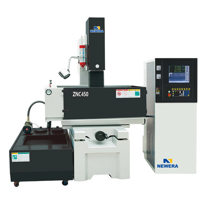
The price difference between EDM machines lives in the control system, not in the tank. A ZNC machine has servo control on the Z axis only: X and Y are positioned by hand and each pass is a simple down-feed with retract. It is inexpensive, robust, and still the right answer for single-cavity work with a shaped electrode.
A PNC machine adds programmable Z-axis cycles, multi-stage retract and stored depths, which shortens setup and improves flushing on deeper work. Full CNC adds servo control on X, Y and often C, so the electrode can orbit, sweep and spiral. The same electrode cuts different sizes by changing the orbit radius, flushing can be repositioned automatically, and several cavities run unattended.
Across the range these three control levels split by work-table size as much as by electronics, and the die-sinking EDM machines are grouped along exactly those lines.
A compact example of the fully programmable end is the CNC-450, a small-table machine that still carries orbiting and multi-pass finishing, which is normally enough for insert work and small multi-cavity moulds.
 CNC 450 EDM Die Sinking MachineCompact CNC-controlled sinker EDM with optional Panasonic servo electrical box, presented for insert work and small multi-cavity moulds.View Product →
Matching the Machine to the Work, Not the Other Way Round
Three numbers decide whether a quoted job actually fits: work-table travel, work-tank dimensions and maximum electrode weight. Travel sets the largest cavity you can position, the tank sets the largest workpiece you can submerge, and electrode weight sets how heavy a graphite blank the head can carry without losing gap control.
Roughing current is the second trap. A large generator on a small machine is not an advantage. Heavy roughing with a big electrode needs flushing volume that a compact tank cannot deliver, so the machine ends up running well below its rated current to avoid arcing, which means you paid for capability you cannot use.
In practice a mid-size machine covers most mould-plate work: the CNC-650, for instance, pairs a larger table and tank with a generator sized to match them, which is the configuration that keeps roughing current, flushing and servo response in balance.
 CNC 650 EDM Die Sinking MachineMid-size CNC die-sinking EDM with optional Panasonic servo electrical box, balancing roughing current, flushing and servo response for mould-plate work.View Product →
Deep Cavities and Large Moulds: The Real Limit
Deep cavities expose the genuine limit of EDM, which is debris evacuation. As depth increases, the flushing area shrinks relative to the gap volume, carbon particles stay trapped, and the discharge becomes unstable no matter how the generator is set. Through-electrode flushing, periodic electrode retraction and running less current than the machine can theoretically deliver are the standard countermeasures.
On large work such as mould bases, die blocks and deep ribs, the practical ceiling is set by Z travel, tank size and machine rigidity rather than by peak current, so machines in this class are specified around structure and flushing logistics. A model such as the CNC-1260, with a substantially larger table and tank, exists for exactly that class of work.
 CNC 1260 EDM Die Sinking MachineLarge CNC die-sinking EDM for mould bases, die blocks and deep ribs, where Z travel, tank size and rigidity define the working ceiling.View Product →
EDM Machining: Frequently Asked Questions
Q1: How does EDM machining work in one sentence?
It removes metal with controlled electrical sparks inside a dielectric fluid; the electrode never touches the workpiece, so hardness does not limit the process.
Q2: What is the difference between sinker EDM and wire EDM?
Sinker EDM uses a shaped copper or graphite electrode to burn a three-dimensional cavity, while wire EDM uses a thin moving wire to cut a two-dimensional profile through the part.
Q3: Can EDM machine hardened steel?
Yes. Hardened tool steel at 62 HRC and beyond is routine work, and cemented carbide can be machined as long as it conducts electricity.
Q4: What is the spark gap in EDM machining?
Typically 0.01 to 0.05 mm on finishing passes and up to about 0.1 mm on roughing, which is why electrodes are cut undersize by the width of that gap.
Q5: How accurate is EDM machining?
Tolerances of roughly 0.005 to 0.02 mm are achievable on a well-maintained sinker EDM, provided electrode wear and gap condition are controlled pass by pass.
Q6: What is the difference between a ZNC, PNC and CNC EDM machine?
ZNC controls only the Z axis with manual X and Y positioning, PNC adds programmable Z cycles, and CNC adds driven axes and orbiting for automatic multi-cavity work.
If you are interested in our products, please consult us.
CONTACT DETAILS
Nantong New Era Technology Co., LTD
- Five-star Industrial Park, Chongchuan District, Nantong City, Jiangsu Province, China
- TEL:+86-19851302688
- E-Mail: [email protected]
Products
Quick link
Mobile terminal
